By Rectron 121
MMBT3904 is an NPN type small signal general purpose transistor. It is a low-power, high-frequency transistor commonly used in amplification and switching applications, especially in the low to mid-frequency range.
MMBT3904 is a small signal surface mount transistor, which is an integrated circuit system. It is an NPN transistor with a maximum collector current of 200mA, a maximum collector-emitter breakdown voltage of 40V, and a maximum power of 200mW. Its DC current gain is 100 under the conditions of 10mA and 1V, and the characteristic frequency is 300MHz.
MMBT3904 is commonly used in analog and digital circuits such as amplifiers, oscillators, pulse generators, logic gates, etc. It is widely used in electronic devices due to its small package and ease of use.
Ⅰ.Specification parameters of MMBT3904
•Number of pins:3
•Number of transistors:1
•Configuration:Single
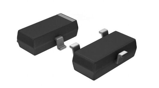
•Package/Case:SOT-23
•Transistor polarity:NPN
•Total power, Ptot:350mW
•Noise factor (NF), maximum:5dB
•Transistor type:general small signal
•Minimum operating temperature:-55℃
•Maximum operating temperature:+150℃
•Installation style:SMD/SMT
•Pd-Power dissipation:350 mW
•Gain bandwidth product fT:300 MHz
•Maximum DC current gain hFE:300
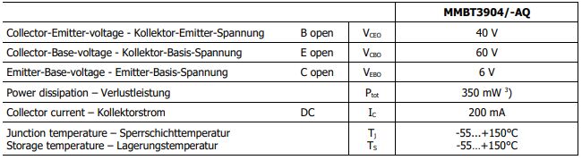
•Emitter-base voltage VEBO:6 V
•Collector-base voltage VCBO:60 V
•Collector-emitter saturation voltage:300 mV
•Maximum DC collector current:200 mA
•Collector-emitter maximum voltage VCEO:40 V
•Product Category:Bipolar Transistor-Bipolar Junction Transistor (BJT)
•Current-collector cutoff (maximum):50nA
•Product type:BJTs-Bipolar Transistor
•DC current gain (hFE) (minimum value) at different Ic, Vce:100 @ 10mA, 1V
Ⅱ.Working principle of MMBT3904
•MMBT3904 is an NPN type small signal surface mount transistor whose working principle is based on the basic principles of semiconductor physics.
•When forward bias is applied between the base and emitter of MMBT3904, the diode conducts, allowing current to flow. This is because the forward bias makes the PN junction between the base and emitter conductive, forming a conductive channel. At this time, when a voltage is applied between the collector and emitter, current will flow from the emitter to the collector through this conductive channel, forming a collector current.
•This property of MMBT3904 makes it widely used as switches and signal amplifiers in electronic circuits. As a switch, it can control the current on and off by controlling the voltage between the base and emitter, thereby realizing the switching function of the circuit. As a signal amplifier, it can apply the input signal to the base and amplify the signal by controlling the size of the collector current to achieve the signal amplification function.
•It should be noted that the operating status of MMBT3904 is affected by bias conditions and voltage limitations. During use, it is necessary to reasonably control the size of the base current and the voltage between the collector-emitter and collector-base to ensure that the transistor works within the normal working area and avoid overload or damage.
Ⅲ.Static operating characteristics of MMBT3904
1.Internal resistance characteristics: The internal resistance of MMBT3904 is low, which means that it produces less energy loss when current flows, thereby improving the overall efficiency. This is very important for circuit applications that require high efficiency.
2.Maximum ratings: Static operating characteristics also include the maximum ratings of the transistor, such as maximum collector-emitter voltage (VCEO), maximum collector-base voltage (VCBO), maximum collector current (IC), and maximum Power consumption, etc.
3.Voltage characteristics: MMBT3904 has a wide operating voltage range, which allows it to work in a variety of voltage environments. Specifically, its collector-emitter breakdown voltage is a maximum of 40V, which means it can safely operate at anything below this voltage.
4.Input and output characteristics: Static operating characteristics also include the input and output characteristics of the transistor. The input characteristics describe the relationship between the base voltage and the base current, while the output characteristics describe the relationship between the collector voltage and the collector current. These properties are usually represented in the form of graphs or curves. ,
5.Current characteristics: The maximum continuous collector current of MMBT3904 is 200mA. This means that under normal operating conditions, it can handle currents up to 200mA reliably.
6.Static operating point (Q point): The static operating point refers to the working state of the transistor under static conditions, usually expressed as the values of collector voltage and collector current. Selecting an appropriate quiescent operating point is critical to amplifier design because it determines the linear range of the transistor during operation and the gain and bias stability of the amplifier.
7.Saturation zone and cut-off zone: Under static conditions, the MMBT3904 can be in one of two main operating states: saturation zone or cut-off zone. In the saturation region, the voltage between the base and emitter is high enough to ensure that the voltage between collector and emitter is below some minimum value (usually a few hundred millivolts), causing current to flow through the entire transistor. In the cutoff region, the voltage between the base and emitter is too low, or the voltage between the base and collector is too high, so that no current flows through the transistor.
Ⅳ.Maximum Ratings of MMBT3904
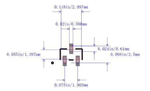
Ⅴ.Pin layout of MMBT3904

•Pin1: Emitter (E), usually an n-type area
•Pin2: Base (B), usually a p-type area
•Pin3: Collector (C), usually an n-type area
Ⅵ.Circuit application example of MMBT3904
1.Switching power supply: MMBT3904 is also widely used in switching power supply. Switching power supply is a type of power supply commonly used in modern electronic equipment. As a switching element, MMBT3904 can achieve fast and efficient control, improve the efficiency of the power supply and reduce the waste of energy. The working principle of the switching power supply is to quickly switch the on-off state of the switching element (such as a triode) to convert the input voltage into a high-frequency pulse voltage, and then transform the voltage and current through components such as a transformer or inductor, and finally through rectification and Filter to obtain a stable output voltage. When using MMBT3904 as a switching element, special attention needs to be paid to its operating voltage, current and frequency limitations to ensure its safe and reliable operation.
2.Oscillator: MMBT3904 can be used to design radio frequency (RF) and audio (AF) oscillators, such as local oscillators, voltage controlled oscillators (VCO), etc.
•For radio frequency (RF) applications, the MMBT3904 can be used in small, low-cost oscillator designs. The oscillation frequency can be controlled by appropriately adjusting external circuit components such as resistors, capacitors, and inductors. In addition, the low noise characteristics of the MMBT3904 make it particularly useful in applications requiring high sensitivity, such as radio receivers and synthesizers.
•Audio (AF) oscillator is used to generate audio signals. By configuring the triode in a suitable circuit and using appropriate frequency control components such as variable resistors or transformers, the frequency and amplitude of the resulting audio signal can be adjusted.
•Voltage controlled oscillator (VCO) is a type of oscillator whose oscillation frequency can be controlled by voltage. In a VCO design, the base of the MMBT3904 usually receives a control voltage, which determines the output frequency of the oscillator. This characteristic makes VCO widely used in communication systems, such as FM broadcasting and wireless communications.
3.Current amplifier: MMBT3904 can be used to design current amplifiers to amplify input current signals to higher current levels. When designing a current amplifier, the amplification factor of the MMBT3904 is a key parameter. This parameter determines the ratio between the output current and the input current, that is, the current amplification factor.
4.Current source: MMBT3904 can also be used to build a constant current source for various applications, such as LED driving, battery charging, etc. With proper circuit design, the characteristics of the triode can be exploited to produce a stable current output.
•LED drive circuit: When using LED, in order to ensure the stable brightness of the LED and prevent it from being damaged by overheating, it is usually necessary to provide it with a constant current. For this purpose, a constant current source based on MMBT3904 can be designed to drive the LED.
•Battery charging circuit: In battery charging applications, MMBT3904 can ensure the safety of the battery and extend its life. It is usually necessary to limit the charging current.
5.Voltage regulator: MMBT3904 can be used in combination with other devices and designed as a voltage stabilizing circuit or current source to provide stable voltage or current output.
•Voltage stabilization circuit: The purpose of the voltage stabilization circuit is to provide a constant output voltage even when the input voltage changes or the load changes. Design a simple voltage regulator circuit using the MMBT3904, typically using a combination of resistors, capacitors and possibly other voltage regulation components such as a Zener diode or linear voltage regulator.
•Current source: Current source circuit is used to provide a constant current output. A more complex design uses the MMBT3904 in conjunction with an operational amplifier (Op-Amp) to implement a precision current source.
6.Temperature sensor: Combined with appropriate sensor components, MMBT3904 can be used to design temperature sensors to measure the ambient temperature and output corresponding electrical signals.
•Use a thermistor: A thermistor is a component whose resistance changes with temperature. When the ambient temperature changes, the resistance of the thermistor will change accordingly. By connecting the thermistor to the MMBT3904 and utilizing the amplification characteristics of the triode, a sensor circuit that converts temperature changes into voltage or current changes can be designed.
•Use integrated temperature sensors: Integrated temperature sensors can also be used, such as LM35, etc. These sensors can directly output a voltage proportional to the temperature. MMBT3904 can be used here as an amplifier or buffer to improve signal stability or drive subsequent circuits.
•Signal processing: MMBT3904, as a transistor, usually plays the role of amplification or buffering in sensor circuits. With appropriate circuit design, the weak signal output by the sensor can be amplified, making it easier to be processed or read by subsequent circuits.
7.Signal detector: MMBT3904 can be used to design signal detectors to detect and analyze the presence, strength, frequency and other characteristics of signals.
•Signal presence detection: MMBT3904 can be used as an amplifier to detect the presence of weak signals. When an input signal is applied to the base of a transistor, if the signal is strong enough to overcome the base-emitter threshold voltage, the transistor will begin to conduct and produce an amplified signal at the collector. By monitoring the output of the collector, the presence of an input signal can be determined.
•Signal strength measurement: By adjusting the amplification factor and feedback network of MMBT3904, a circuit capable of measuring signal strength can be designed. Typically this involves amplifying the signal to an appropriate level, then using some form of attenuator or voltage divider to reduce the signal strength and quantizing it via a comparator or ADC (analog-to-digital converter).
•Frequency detection: MMBT3904 can be used to build a simple frequency detector. For example, by exploiting the resonant properties of a triode, it is possible to design a circuit that responds to a specific frequency. Alternatively, you can convert the signal to a square wave and then use a counter to measure the number of square waves per unit time to deduce the frequency of the signal.
8.Voltage drive: MMBT3904 can be used to drive other electronic components, such as LEDs, relays, etc. By connecting transistors in appropriate circuits, smaller control signals can be used to control larger currents to drive these components.
•LED driver: MMBT3904 can be used as an LED driver circuit. By connecting the positive terminal of the LED to the collector of the triode and the negative terminal of the LED to ground, the LED can be controlled to turn on and off. When the base receives the appropriate control signal, the transistor turns on, allowing current to pass through the LED, causing it to emit light. By adjusting the voltage or current of the control signal, the brightness of the LED can be controlled.
•Relay driver: MMBT3904 can also be used to drive relays. A relay is a device that controls the switching of large currents through electromagnetic effects. By connecting the MMBT3904 to the control coil of the relay and using a smaller control signal to drive the transistor on, a magnetic field can be generated in the coil of the relay to drive the contact switch of the relay.
9.Switch application: MMBT3904 can be used as a switching element in digital logic circuits, pulse generators, etc. By controlling the voltage of the base, the on and off states of the triode can be controlled, thereby achieving switching control of the circuit.
10.Signal amplification: MMBT3904 is often used as a low-power signal amplifier, such as audio amplifier, sensor signal conditioning, etc. In these applications, transistors can amplify weak input signals for further processing or to drive other devices.
Ⅶ.Package diagram of MMBT3904
Ⅷ.Replacement model of MMBT3904
•2SC5200
•BC549
•BC639
•BC636
•2N2222
•2N3055
•2N2369
•2N3906
Frequently Asked Questions
1.How does MMBT3904 operate in a circuit?
MMBT3904 operates as an amplifier or a switch depending on the biasing conditions. In an amplifier circuit, it amplifies small input signals, while in a switch circuit, it controls the flow of current between its collector and emitter.
2.Can MMBT3904 be used in high-frequency applications?
Yes, MMBT3904 can be used in high-frequency applications due to its relatively high gain bandwidth product.
3.Is MMBT3904 suitable for low-power applications?
Yes, MMBT3904 is suitable for low-power applications due to its low power dissipation and small size.
4.What is the maximum voltage rating of MMBT3904?
The maximum collector-emitter voltage (VCEO) rating of MMBT3904 is usually around 40V.